In this tutorial I will explain the mechanical assembly robot Andromina, step by step, in a simple manner and with the use of very simple tools. Little tricks for assembling and improving the robot is also discussed. I would appreciate it if there is any way that is not clearly explain, I requested the information further enlargement. You have to keep in mind that this robot is not a toy and more like a professional robot a toy.
 |
| Robotic platform Andromina v.1.2 OFF ROAD., Assembled. |
 |
| Lateral view of the robotic platform. |
Tools required:
For the assembly we will need several simple tools such as a mini screwdriver and a flat,
scissors, Allen wrench
2.5mm,
5.5mm fixed wrench, a soldering iron and tin.
 |
| The drwing and dimensions of the robot. |
 |
| Basic exploded view of the Andromina robot v1.2 OFF ROAD. |
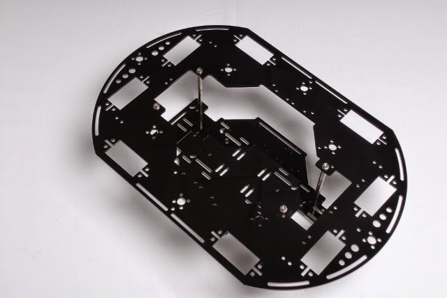
Chassis: Main parts of the robot chassis are 2 acrylic plates, the superior plate and the inferior plate. The assembly of the chassis is shown in the picture above:
 |
| Basic exploded view of robot chassis. |
 |
| Chassis assembly. |
Upper chassis:
Lower chassis:
 |
| View of the 4 servomotors |
 |
| Servo chassis seen from the bottom. |
 |
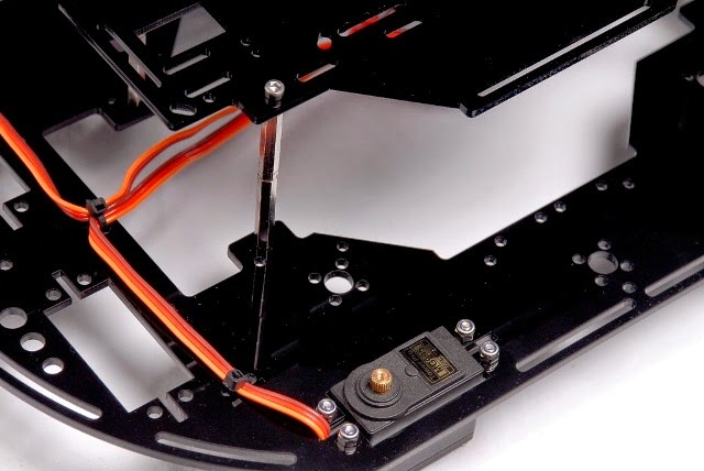
| Detail of an assembled servomotor. |
 |
| Detail of electrical cables a servomotor |
 |
| Two motors, one with a capacitor and wire |
 |
| Graph of voltage versus time without capacitador. . |
 |
| Graph of voltage versus time with capacitador. |
 |
| Arduino UNO wiring diagram for calibration of the 4 servo motors. |


No comments:
Post a Comment